Solar Power Factor Correction plays a vital role in modern electrical systems, providing tangible economic and ecological benefits. As technology continues to evolve, the methods and applications of PFC are sure to expand, reinforcing its essential role in our energy-dependent world.
Table of content
- I. Introduction
- II. Understanding Power Factor
- III. Types of Power Factor Correction
- IV. Devices and Design
- V. Application Areas
- VI. Implementation Techniques
- VII. Regulations and Compliance
- VIII. Power Factor Correction Solutions
- IX. Case Studies and Examples
- X. Vendor Analysis and Equipment
- XI. Regional Perspectives
- XII. Future Directions and Challenges
- XIII. Appendices
- XIV. Conclusion
I. Introduction
Definition of Solar Power Factor Correction
Power Factor Correction (PFC) is a technique used to align the electrical current drawn by a load more closely with the electrical power’s voltage wave. By reducing the angle between these two waves, the power factor becomes closer to a perfect value of 1, thereby making the electrical system more efficient. PFC is utilized in both industrial and residential applications to minimize losses and enhance the utilization of electrical power.
Importance of Solar Power Factor Correction
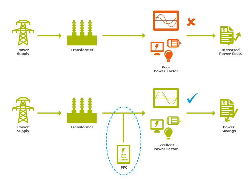
The significance of PFC cannot be understated. A low power factor signifies that an electrical system is drawing more current than necessary, leading to the following challenges:
- Increased Transmission Losses: The higher current leads to more losses in the transmission lines, wasting energy.
- Utility Penalties: In some regions, utilities may impose penalties on commercial customers with a low power factor.
- Oversized Equipment: Without PFC, transformers, generators, and other equipment must be larger to handle the increased current, leading to higher costs.
- Reduced System Capacity: The additional current can lead to premature equipment failure and reduce the overall capacity of the electrical system.
Power Factor Correction provides a solution to these problems, offering economic and environmental advantages by increasing efficiency and reducing energy consumption.
Historical Perspective
The concept of power factor correction dates back to the early days of electrical engineering. With the growth of industrialization and the increase in inductive loads such as motors and transformers, the need for PFC became apparent.
In the 20th century, the use of capacitors for PFC became common. The development of solid-state technology further advanced the field, leading to more sophisticated and effective power factor correction methods.
Today, PFC is a vital aspect of modern electrical systems, with various techniques and devices designed to cater to different applications, from residential to heavy industrial.
Application across Industries
PFC is widely used across various sectors to enhance electrical efficiency:
- Industrial: In manufacturing plants, PFC is often used to counteract the effects of large inductive loads, such as motors and industrial machinery.
- Commercial: In commercial buildings, PFC can be used to reduce energy bills and comply with local regulations.
- Residential: Even in homes, PFC devices can be installed to improve the efficiency of household appliances and reduce electricity costs.
- Renewable Energy: In renewable energy systems like wind and solar farms, PFC is critical to maintain stability and efficiency in the electrical grid.
II. Understanding Solar Power Factor
Explanation of Solar Power Factor
Power Factor (PF) is a critical concept in the world of electrical engineering. It defines the ratio of real power (P) used to do work to the apparent power (S), which is the total power in the system. A Power Factor of 1 (or 100%) means all the power is effectively converted into work. In real-world applications, the Power Factor typically ranges from 0.8 to 0.95.
Leading and Lagging Solar Power Factor
Understanding the difference between leading and lagging Power Factor is crucial:
- Leading Power Factor: Occurs when the load is predominantly capacitive. Here, voltage leads the current, meaning the current wave reaches its peak after the voltage does.
- Lagging Power Factor: Occurs when the load is primarily inductive, such as in motors or transformers. In this case, current lags behind voltage, meaning the current wave reaches its peak later than the voltage wave.
The difference has significant impacts on the efficiency and safety of an electrical system.
Solar Power Factor Triangle
The Power Factor Triangle is a visual representation of the relationship between real, reactive, and apparent power:
- Real Power (P): The actual power used in the circuit (measured in Watts).
- Reactive Power (Q): Represents the power that oscillates between the source and load (measured in Volt-Amperes Reactive or VAR).
- Apparent Power (S): The total power in the system (measured in Volt-Amperes or VA).
The Power Factor can be expressed as the cosine of the angle between the apparent power and real power (cos θ = P/S).
Calculation Methods
- Manually: Power Factor can be calculated using the formula PF = P / S.
- Using Instruments: Specialized devices like Power Factor meters can directly measure the Power Factor.
How to Calculate kVAR for Solar Power Factor Correction
Calculating the kVAR (kilo Volt-Amperes Reactive) for Power Factor correction involves determining the reactive power required to achieve a desired Power Factor. The formula is:
kVAR=kVA×sin(arccos(desired PF))−kVA×sin(arccos(current PF))
Solar Power Factor Correction Formula in Excel
Excel can be a powerful tool for calculating Power Factor and related values. By setting up cells with the above formulas, you can create a template that automatically calculates the required kVAR for Power Factor correction. Here’s a simple example:
- Enter the current kVA in cell A1.
- Enter the current Power Factor in cell B1.
- Enter the desired Power Factor in cell C1.
- In cell D1, enter the formula:
excel code
=A1*SIN(ACOS(C1)) - A1*SIN(ACOS(B1))
The result in cell D1 will be the required kVAR for Power Factor correction.
III. Types of Solar Power Factor Correction
Power Factor Correction (PFC) is a technique used to improve the Power Factor in an electrical system, enhancing its efficiency. PFC can be classified into different types based on the methods and technologies used. In this section, we will explore the various types of PFC.
A. Active Power Factor Correction (APFC)
Active Power Factor Correction employs active electronic components like ICs and programmable logic controllers (PLCs) to align the voltage and current waveforms. APFC systems continuously monitor the Power Factor and dynamically adjust the compensation.
Advantages:
- Highly effective in correcting Power Factor.
- Adaptable to varying load conditions.
Disadvantages:
- More complex and costly compared to passive methods.
B. Passive Power Factor Correction (PPFC)
Passive Power Factor Correction involves using passive elements like capacitors and inductors to offset the inductive effects of the load.
Advantages:
- Simple and low-cost solution.
- Suitable for constant loads.
Disadvantages:
- Less effective for variable loads.
C. 3 Phase Power Factor Correction
Three-phase Power Factor Correction is used in industrial and heavy commercial applications where three-phase power is common.
Advantages:
- Suitable for large and fluctuating loads.
- Efficient in handling imbalances between phases.
Disadvantages:
- Complexity in implementation and maintenance.
D. Single Phase Power Factor Correction
Single Phase Power Factor Correction is commonly used in residential and light commercial applications.
Advantages:
- Simpler and less expensive compared to three-phase systems.
- Suitable for smaller loads.
Disadvantages:
- Not suitable for large industrial applications.
E. Power Factor Correction in SMPS (Switched-Mode Power Supply)
Switched-Mode Power Supplies often incorporate Power Factor Correction to minimize energy loss and comply with regulatory standards.
Advantages:
- Improves overall efficiency of the SMPS.
- Reduces harmonic distortion.
Disadvantages:
- Adds complexity to the design of the SMPS.
Each method of Power Factor Correction has its unique applications, advantages, and drawbacks. Choosing the appropriate technique depends on various factors, including the type of load, the magnitude of correction required, budget constraints, and specific operational requirements. Understanding these methods helps in selecting the optimal solution for different scenarios, ultimately leading to enhanced energy efficiency and compliance with industry standards.
IV. Devices and Design
Power Factor Correction (PFC) requires specific devices and design strategies to adapt to different applications and requirements. From PFC boxes to specialized capacitors and ICs, various tools can be utilized. Let’s delve into the essential devices and design aspects involved in PFC.
A. Power Factor Correction Box
A Power Factor Correction Box is a ready-made solution that includes all necessary components for PFC, encapsulated in a single unit.
Advantages:
- Easy to install and maintain.
- Suitable for both residential and commercial applications.
B. Power Factor Correction Capacitor
These capacitors are specially designed to provide reactive power compensation. They are available in different ratings, such as 1 kVAR, 10 kVAR, etc., depending on the application’s needs.
Advantages:
- Efficient in compensating reactive power.
- Available in various ratings to suit different requirements.
C. Power Factor Correction IC
Integrated Circuits (ICs) for PFC are electronic components designed to control and manage the power factor in various devices, such as SMPS.
Advantages:
- Precision control and regulation.
- Ideal for compact and complex applications.
D. Power Factor Correction Transformer
Transformers designed for PFC are used to alter the voltage level and provide phase-shifting capabilities, aiding in Power Factor optimization.
Advantages:
- Suitable for large-scale industrial applications.
- Effective in phase balancing.
E. Power Factor Correction Design
1. Software
Design software enables engineers to model and simulate PFC circuits, optimizing them for performance and efficiency.
2. PDF Guides
PDF guides provide comprehensive information, diagrams, and step-by-step instructions for designing PFC systems.
3. Design Guidebooks
Books and manuals on PFC design provide detailed insights, best practices, and expert guidance.
F. Power Factor Correction using Arduino
Arduino microcontrollers can be programmed to control PFC systems. Code for Arduino-based PFC can be customized to suit specific applications.
Advantages:
- Affordable and flexible solution.
- Suitable for DIY projects and educational purposes.
V. Application Areas
Power Factor Correction (PFC) plays an essential role in various application areas, ranging from industrial machinery to home appliances and modern electric vehicles. It is implemented to optimize energy usage, reduce energy costs, and minimize the strain on the power grid. Here’s a look at some significant application areas of PFC.
A. Power Factor Correction in Diesel Generators
Diesel generators often run at fluctuating loads, leading to a varying power factor. Implementing PFC in these generators:
- Improves fuel efficiency.
- Extends the life of the generator.
- Reduces harmful emissions.
B. Power Factor Correction in UPS (Uninterruptible Power Supply)
UPS systems must maintain a consistent power factor to deliver stable and reliable power.
- Ensures uninterrupted power during outages.
- Enhances the efficiency of the UPS system.
- Minimizes heat generation, thus extending the lifespan of the UPS.
C. Power Factor Correction in Inverter
Inverters convert DC to AC and are found in numerous applications. PFC in inverters:
- Improves overall system efficiency.
- Enables smooth functioning of connected devices.
- Reduces harmonic distortions in the output.
D. Power Factor Correction in AC Circuit
AC circuits are ubiquitous in homes and industries, and PFC helps in:
- Minimizing energy losses.
- Reducing electricity bills.
- Enhancing the lifespan of connected devices.
E. Power Factor Correction for Home
Home appliances and systems can benefit significantly from PFC:
- Lowers energy consumption, leading to cost savings.
- Reduces wear and tear on home electrical systems.
- Enhances the performance of appliances like air conditioners, refrigerators, etc.
F. Power Factor Correction for Electric Vehicle (EV)
As EVs become more prevalent, PFC in charging systems and onboard power management becomes crucial:
- Improves charging efficiency, reducing charging time.
- Enhances battery life and overall vehicle performance.
- Supports the broader adoption of green transportation by optimizing energy usage.
VI. Implementation Techniques
- Power Factor Correction Algorithm
- Power Factor Correction Techniques
- Power Factor Correction with Interleaved Boost
- Power Factor Correction by Using Capacitor Bank
- Power Factor Correction with Flyback Converter Employing Charge Control
VII. Regulations and Compliance
Compliance with regulations and requirements is a vital aspect of Power Factor Correction (PFC) implementation. These rules ensure that power systems operate efficiently and safely while minimizing their environmental impact. Here, we explore the various requirements, standards, and permitting processes related to PFC.
A. Power Factor Correction Requirements
General PFC requirements vary across different countries and regions. They may encompass the following:
- Energy Efficiency Standards: Ensuring that the PFC devices meet the desired efficiency ratings.
- Safety Regulations: Compliance with safety standards to protect both equipment and personnel.
- Environmental Considerations: Regulations related to reducing harmonic disturbances and emissions.
B. Power Factor Correction Regulations in the UK
In the United Kingdom, specific regulations govern PFC. These include:
- The Electricity Act: Outlines the legal obligations of electricity suppliers and consumers in maintaining the quality of electricity supply.
- Distribution Network Operator (DNO) Requirements: Specific rules from local DNOs that may stipulate certain power factor levels.
- EU Standards and Directives: Compliance with relevant European standards, especially in the context of energy efficiency and environmental protection.
C. Permitting and Power Factor Correction Installation
Before implementing a PFC system, particularly in industrial or large commercial settings, various permits and approvals may be necessary:
- Local Authority Approvals: Depending on jurisdiction, local government or regulatory bodies may require permits for the installation of PFC equipment.
- Compliance with Electrical Codes: Ensuring that the installation complies with national and local electrical codes.
- Inspections and Certifications: Post-installation inspections may be necessary to certify that the PFC system meets all regulatory and safety standards.
- Coordination with Utility Companies: In some cases, coordination with the local utility provider may be needed to ensure that the PFC system aligns with their requirements.
VIII. Power Factor Correction Solutions
Power Factor Correction (PFC) solutions are designed to optimize the efficiency of electrical systems, reduce energy costs, and comply with regulations. These solutions come in various forms, such as panels, systems, relays, and calculators, to meet the specific needs of different applications. In this section, we’ll explore some of the common PFC solutions.
A. Power Factor Correction Panel Design
PFC panels are central to many correction solutions. They house the necessary components like capacitors, relays, and controllers. The design of these panels must consider:
- Size and Rating: The size and rating must align with the kVAR needs of the system.
- Component Layout: Effective layout to ensure accessibility and safe maintenance.
- Cooling and Ventilation: Adequate cooling mechanisms to prevent overheating.
- Compliance with Standards: Adherence to local and international electrical standards.
B. Power Factor Correction System (125kVAR, 150 kVAR, etc.)
PFC systems are tailored to the specific needs of an application, ranging from small commercial settings to large industrial complexes. Key considerations include:
- Capacity Selection: Choosing the correct kVAR rating (e.g., 125kVAR, 150 kVAR) based on load requirements.
- Type of Correction: Whether active, passive, or hybrid PFC systems are most suitable.
- Integration with Existing Systems: Ensuring compatibility with current electrical infrastructure.
- Monitoring and Control: Including features for real-time monitoring and automatic adjustments.
C. Power Factor Correction Relay
PFC relays are essential components that control the switching of capacitors to maintain the desired power factor. These relays offer:
- Intelligent Control: Automatic adjustments to match varying load conditions.
- Protection Features: Safeguarding against over-voltage, under-voltage, and other abnormal conditions.
- Ease of Integration: Compatibility with various types of PFC systems.
D. Power Factor Correction Savings Calculator
To estimate the potential savings and benefits of implementing PFC, savings calculators can be a valuable tool. These calculators typically allow users to:
- Input Load Conditions: Include details about current power factor, energy rates, and consumption patterns.
- Calculate Potential Savings: Estimate the monetary savings and efficiency gains from PFC.
- Assess ROI: Determine the return on investment for different PFC solutions.
IX. Case Studies and Examples
Understanding power factor correction (PFC) through practical examples and case studies can provide valuable insights into the real-world applications, challenges, and solutions related to PFC. This section delves into specific instances that highlight different aspects of PFC.
A. Power Factor Correction Example
Example: Upgrading a Manufacturing Plant
A medium-sized manufacturing plant experienced poor power factor ratings averaging around 0.7. An assessment revealed inefficient motors and lack of capacitive compensation.
Solution:
- Installation of a 100kVAR PFC system with proper capacitor sizing.
- Retrofitting motors with energy-efficient alternatives.
- Continuous monitoring and adjustments to adapt to load variations.
Outcome:
- Improved power factor to 0.95, reducing utility penalties.
- Lower energy consumption leading to annual cost savings.
B. Power Factor Correction Fault Analysis
Case Study: Fault in a Commercial Complex
A commercial complex’s PFC system encountered recurrent faults, leading to significant drops in power factor and efficiency.
Analysis:
- Detailed investigation into the PFC panel found faulty relays and improperly sized capacitors.
- The maintenance routine was inconsistent, leading to undetected issues.
Solution:
- Replacing the faulty components and recalibrating the system.
- Implementing a regular maintenance schedule with proper documentation.
Outcome:
- Restored optimal performance of the PFC system.
- A more proactive approach to maintenance to prevent future faults.
C. Power Factor Correction Problem Solutions
Example: Addressing PFC in a Hospital Setting
A large hospital struggled with fluctuating power factor due to a mix of inductive and nonlinear loads, leading to inefficiency and instability.
Challenges:
- Diverse load profiles with varying requirements.
- Need for uninterrupted power, given the critical nature of healthcare operations.
- Compliance with stringent regulations.
Solutions:
- Implementation of a hybrid PFC system to cater to both inductive and nonlinear loads.
- Regular audits to assess performance and adherence to regulations.
- Education and training for staff to ensure proper operation and monitoring.
Outcome:
- Achieved stable and efficient power supply across the hospital.
- Compliance with regulatory standards, ensuring patient safety and operational continuity.
X. Vendor Analysis and Equipment
Choosing the right vendor for power factor correction (PFC) equipment is crucial in ensuring quality, reliability, and efficiency. This section analyzes some of the major players in the PFC market, their offerings, and what sets them apart.
A. Power Factor Correction Dell
Dell is known for its technology solutions, including power management and PFC.
Products:
- Active Power Factor Correction units for data centers.
- Integrated PFC solutions for servers and network equipment.
Strengths:
- Energy-efficient designs that align with global standards.
- Tailored solutions to meet the specific needs of various industries.
- Strong customer support and global presence.
B. Power Factor Correction Schneider
Schneider Electric is a leader in energy management, offering a wide array of PFC products.
Products:
- Automatic and static power factor correction panels.
- Capacitor banks and harmonic filtering solutions.
Strengths:
- Innovative designs with advanced monitoring and control capabilities.
- Robust solutions that can handle diverse industrial applications.
- Comprehensive support and services, including consulting and training.
C. Power Factor Correction Eaton
Eaton Corporation specializes in power management, with an extensive range of PFC solutions.
Products:
- Complete PFC systems, including capacitors, controllers, and relays.
- Power factor correction for commercial, industrial, and utility applications.
Strengths:
- High-quality components that ensure longevity and performance.
- Flexible solutions that can be customized to specific requirements.
- Global reach with local expertise and support.
D. Other Power Factor Correction Manufacturers
There are many other manufacturers in the PFC market offering specialized solutions.
Examples:
- ABB: Known for energy-efficient PFC products.
- Siemens: Offers comprehensive PFC systems for various applications.
- General Electric (GE): Provides advanced PFC solutions with innovative technologies.
Considerations for Selection:
- Understanding the specific needs and load profiles of your application.
- Assessing the reputation, experience, and certifications of the manufacturer.
- Comparing the features, pricing, and support provided by different vendors.
The selection of PFC equipment and vendors must be aligned with the specific requirements, budget, and goals of the application. Understanding the strengths and offerings of key vendors like Dell, Schneider, and Eaton can help in making an informed decision.
Furthermore, engaging with the vendors, exploring customization options, seeking expert opinions, and considering local compliance and regulations can ensure a PFC solution that is robust, efficient, and in line with the organization’s needs. Careful planning and consideration can lead to a successful implementation that delivers tangible benefits and long-term savings.
XI. Regional Perspectives: Solar Power Factor Correction in Australia
Australia’s increasing reliance on solar energy and the corresponding growth in solar installations presents unique challenges and opportunities in power management. Solar power factor correction (PFC) is an essential aspect of this landscape, ensuring efficient energy usage, compliance with regulations, and long-term sustainability.
A. Solar Power Factor Correction: An Overview
Solar power factor correction refers to the techniques and devices used to adjust the power factor in solar energy systems. It ensures that the power is effectively converted and utilized, minimizing losses and improving the overall efficiency of the system.
B. Importance in Australia’s Solar Landscape
- Growing Solar Adoption: Australia is one of the global leaders in solar energy adoption. The vast geography and abundant sunshine make solar power an attractive option.
- Grid Stability: With the increased integration of solar power into the grid, maintaining stability requires effective PFC.
- Regulatory Compliance: Australian energy regulations emphasize efficiency and sustainability, necessitating proper power factor management.
C. Techniques and Solutions in Australia
- Active PFC: Suitable for complex solar installations and large-scale solar farms.
- Passive PFC: Often used in smaller systems, like residential solar installations.
- Hybrid Systems: A combination of active and passive techniques to cater to specific needs.
D. Challenges and Considerations
- Harmonics: Solar inverters can introduce harmonics, requiring careful PFC design.
- Weather Conditions: The varying sunlight conditions must be factored into the PFC solution.
- Cost and Complexity: Implementing PFC in solar systems can be complex and costly, requiring careful planning and expertise.
E. Local Manufacturers and Providers
Several companies specialize in solar PFC solutions in Australia, offering tailored products and services.
XII. Future Directions and Challenges
As technology continues to evolve and the need for efficient energy management intensifies, the area of power factor correction (PFC) is ripe for innovation and transformation. This chapter delves into the future directions and challenges that lie ahead in the field of PFC, including digital control, understanding the disadvantages, and exploring emerging technologies.
A. Digital Control in Power Factor Correction
- Introduction: The advent of digital control systems in PFC has opened up new avenues for more precise and intelligent control over power consumption.
- Advantages:
- Precision: Enables finer control over power correction.
- Integration: Can be integrated with other digital systems for comprehensive monitoring and management.
- Adaptability: Easily adjusted to meet changing needs and demands.
- Challenges:
- Complexity: Requires sophisticated technology and skilled professionals.
- Cost: The initial investment can be higher.
- Examples: Real-world applications of digital control in various industries.
B. Power Factor Correction Disadvantages
While PFC is crucial for efficient energy utilization, it’s not without its challenges and disadvantages:
- Costs: The initial setup and maintenance costs can be prohibitive for smaller businesses.
- Complexity: Designing and implementing a PFC system requires specialized knowledge.
- Potential Issues with Overcorrection: If not carefully managed, PFC can lead to other electrical issues.
- Space Requirements: Physical space needed for PFC equipment.
C. Emerging Technologies in Power Factor Correction
The future of PFC is bright with emerging technologies promising to reshape the field:
- Artificial Intelligence and Machine Learning: These technologies can automate and optimize PFC, adapting to real-time changes in consumption patterns.
- Internet of Things (IoT): Integration with IoT devices can provide more granular control and monitoring.
- New Materials and Components: Research into innovative materials may lead to more efficient and compact PFC devices.
- Hybrid Solutions: Combining different types of PFC to create more versatile and efficient systems.
XIV. Conclusion
A. Summary of Key Concepts
Power Factor Correction (PFC) has become an essential aspect of modern electrical engineering, affecting various applications ranging from industrial machinery to residential electronics. Throughout this eBook, we’ve explored the fundamental principles of power factor, different correction methods, design aspects, applications, challenges, regulations, and vendor considerations. Here’s a concise recap:
- Understanding Power Factor: We delved into the concepts of leading and lagging power factors, visualizing these ideas with the power factor triangle, and learned about the various calculations involved.
- Types of PFC: Exploring both active and passive correction methods, including three-phase and single-phase systems, and their specific applications.
- Devices and Design: This section detailed various devices such as PFC boxes, capacitors, ICs, and transformers, along with design considerations using software and microcontrollers like Arduino.
- Applications and Techniques: We looked at how PFC can be applied across diverse areas, such as diesel generators, UPS, inverters, and even in electric vehicles, with specific techniques and algorithms.
- Challenges, Solutions, Vendors, and Regional Perspectives: These parts encompassed the complexity of PFC’s practical implementation, the tailored solutions available, the key vendors in the industry, and specific considerations like solar power factor correction in Australia.
B. Future Prospects
The landscape of PFC is continuously evolving, shaped by emerging technologies, regulatory shifts, and growing awareness of energy efficiency:
- Digital Control in PFC: With the integration of digital control systems, PFC is advancing towards more precise and intelligent management.
- Emerging Technologies: Innovations such as Artificial Intelligence and IoT may pave the way for new methods and applications in PFC.
- Disadvantages and Challenges: We also addressed some drawbacks and potential hurdles, emphasizing the need for ongoing research and development.
C. Recommendations for Implementation
Implementing PFC is a nuanced process, requiring careful planning, selection, and compliance with regulations. Here are some general recommendations:
- Assessment and Planning: Start with a clear understanding of the energy needs and current power factor situation in the particular application.
- Choosing the Right Method: Select between active and passive PFC, single or three-phase systems, considering the specific requirements.
- Compliance with Regulations: Always adhere to regional and national regulations regarding PFC, such as those in the UK.
- Consulting Experts and Vendors: Engage with professionals and reputable vendors, such as Dell, Schneider, and Eaton, for guidance and high-quality products.
Final Words
The world of Power Factor Correction is intricate yet immensely beneficial, offering avenues for energy efficiency, cost savings, and sustainability. By understanding its principles and applying best practices, individuals and organizations can make informed decisions that align with their goals and regulatory landscape. As technology continues to advance, staying abreast of the latest trends and methodologies will be paramount for success in this field. Whether you’re an engineer, a decision-maker in an organization, or someone keen on energy management, this eBook serves as a comprehensive guide to Power Factor Correction. Thank you for journeying through these pages, and feel free to reach out with questions or feedback. Your path towards a more efficient and responsible energy future starts here.
- Get Started with Solar Today: Request your free quote from Target Solar and explore the best solar solutions for your business.
- Visit Us in Person: Find us on Google Maps and let’s discuss how solar energy can redefine your business.
- Read Real Reviews: Check out our 150+ verified Google reviews and make an informed decision.
Join Target Solar in building a greener future. Contact us today!